

An impulse relay is a control device that switches a circuit on and off in response to electrical pulses sent by push buttons. Each new command changes its contact state. For lighting, it allows the same light to be controlled from several locations, with switching centralised in the distribution board. The Solera TLR16 is a modular reference intended for this type of application.
Start with the behaviour you need from the lighting
If the light must stay on until somebody presses a button again, consider impulse control. If it must switch off by itself after an interval, a timing function is needed. If it must follow a calendar, consider a time switch. These are different requirements: similar modular dimensions do not make the devices functionally interchangeable.
What is an impulse relay and what is it used for?
An impulse relay changes the state of a contact when it receives a momentary command. The user does not have to hold the push button down to keep the lighting on. After the button is released, the circuit retains the selected state; the next pulse triggers another change. This is the basic principle of impulse control.
The arrangement can be considered where one area needs several control points: two entrances to a corridor, different circulation areas in a home, or several entrances to a workspace. The push buttons operate the control circuit and the device performs the switching. This makes it possible to design centralised switching in the board, provided the circuits and protection devices are suitable for the installation.
An impulse relay does not replace overload, short-circuit or electric-shock protection. It is not automatically a dimmer or a connected device either. Switching, dimming, timing and remote control are separate functions. The presence of one does not establish the others, even if products look similar or appear in the same catalogue family.
How an impulse relay works: coil, contact and push buttons
The coil receives the control pulse
The coil is the part that receives the electrical command. A push button produces a brief command and returns to its rest position when released. The coil voltage must match the supply intended for the control circuit. Solera’s TLR16 product sheet specifies a 230 V~, 50/60 Hz coil. This must be distinguished from the electrical characteristics of the circuit being switched.
The contact changes the state of the circuit
The contact opens or closes the circuit on which it acts. In alternating on/off operation, one pulse changes its position and a later pulse changes it again. The TLR16 has one normally open contact, identified as 1 NO in its English documentation.
This differs from a monostable relay, which requires a maintained control command to stay in its operating position. With the impulse function described here, the command is momentary and the selected state remains after the button is released. Behaviour following a power interruption must nevertheless be checked for the exact model. It should not be inferred from another device’s operation.
Impulse relay and latching relay: understanding the terminology
The term latching relay covers a broader group of devices that retain a switching state. For lighting operated by successive push-button pulses, impulse relay describes the required function more precisely. Neither term establishes the coil voltage, contact arrangement or terminal connections. A reference must be selected from its documented operating characteristics, rather than from the name alone.
When should you use an impulse relay for lighting?
The number of control points is only one consideration. Building layout, available wiring, board space and the intended use of the lighting matter as well. A new installation allows these factors to be considered together from the design stage. For a refurbishment, the existing circuit must first be identified: replacing wall mechanisms does not automatically prepare a two-way switching circuit for an impulse relay.
In a home, a corridor with several entrances may need any push button to change the state of the same lighting. An office or commercial space with several access points may present a similar requirement. The design must also establish who will switch the light off and when. If it is likely to remain on unnecessarily, a timing function or another control strategy may suit the use better.
An impulse relay is worth considering when the intended logic is manual: one press switches on and another switches off. Installing it does not guarantee energy savings. The outcome depends on user behaviour, operating hours, installed power and the wider control strategy. Defining the required function is more useful than selecting a familiar device by habit.
Impulse relay, two-way switching, staircase timer or time switch?
Impulse relay: a new state with each pulse
Consider this function when several push buttons must operate the same lighting and retain its state until another command. Switching takes place in the board-mounted device. Before selecting it, verify the coil, contact arrangement, push-button characteristics and load. Do not assume that any number of control points can be connected without checking the circuit and device documentation.
Two-way and intermediate switches: maintained positions
These control lighting from several locations through an arrangement of switch mechanisms and switching conductors. They are an alternative to compare with impulse control for the particular project. A conventional switch retains a mechanical position, whereas a push button returns to rest. The mechanisms cannot be exchanged without checking the complete circuit and intended operating logic.
Staircase timer: lighting for a selected interval
A timing function should be considered when the lighting must switch off automatically after a chosen delay. The Solera AE16/230 staircase timer declares LED suitability in its product sheet. That characteristic belongs to that reference. It must not be transferred to the TLR16 simply because both products share a catalogue family or modular format.
Time switch: operation to a programme
A time switch acts according to a schedule rather than depending solely on local push-button commands. This can be relevant for services with repeated operating times or different hours on different days. The R168D is a digital weekly time switch in Solera’s range. Select the function from the actual schedule and load requirements, rather than from a module’s external appearance.
How to choose an impulse relay: five important checks
1. Coil voltage and control supply
Identify the voltage required by the coil and the supply available in the control circuit. A 230 V~ coil reference is not a replacement for another coil voltage just because the device has the same width or stated current. Frequency and control-signal conditions also need to be checked. The complete product reference helps distinguish variants that may look almost identical.
2. Contact arrangement and switching function
The number of contacts and their configuration determine the possible switching action. Specifying only a 16 A impulse relay is insufficient for a project. Establish whether the required contact is normally open, normally closed or another arrangement, and whether the operating sequence matches the circuit. For the TLR16, the verified configuration is one normally open contact.
3. Connected load, particularly LED inrush current
Steady-state current is only part of the selection process. Electronic lighting equipment and power supplies may draw an inrush current different from their normal running consumption. Adding lamp wattages and dividing by the supply voltage does not, on its own, demonstrate that the switching device is suitable for the installation.
The TLR16’s stated 16 A current is not a universal approval for switching any collection of LED luminaires up to that value. Applicable load conditions and switching capacity must be verified. If the design requires the control command to be separated from switching a larger load, a correctly rated and coordinated contactor arrangement should be assessed. Adding a contactor without checking the complete arrangement is not a substitute for selection.
4. Push buttons and control-circuit conditions
An illuminated push button includes components beyond a simple contact. These may affect the electrical conditions of the control circuit. Check the documentation for both the relay and the wall mechanism before combining them. Cable route, conductor arrangement and the number of control points also belong in the design assessment. There is no universal number that applies to every relay and every installation.
5. Mounting, environment and board access
Check available width, fixing method and environmental conditions. The TLR16 occupies one 18 mm module and is specified for mounting on 35 mm DIN rail. These details help plan its integration, but the complete board still needs assessment: connection space, equipment arrangement, access and circuit protection. An indoor device does not become an outdoor solution simply by being placed in any enclosure.
Impulse-relay wiring diagrams: what to establish before connection
A useful starting point for reading a diagram is to distinguish the control supply, the push buttons that send the pulses and the circuit whose load is switched. This explains the role of the different parts. It does not, by itself, provide the connection diagram for a particular product reference.
Terminal identification, voltages, conductor sizes and protection requirements must come from the applicable documentation and installation design. Do not transfer terminal numbers from another manufacturer’s diagram or infer connections from a product photograph. During a refurbishment, identify the existing wiring before modifying it and establish whether it supports the new arrangement. Connection must be carried out by qualified personnel with the installation isolated from the supply and the required checks completed before commissioning.
Solera TLR16: an example of a modular impulse relay
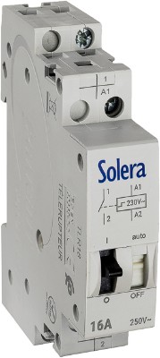
The Solera TLR16 impulse relay is intended for control of installations with lamps or general uses in indoor domestic and commercial environments. Its product sheet identifies the reference and provides the specifications to review before including it in a project.
- Contact: one normally open, 1 NO.
- Stated current: 16 A.
- Coil: 230 V~, 50/60 Hz.
- Modular width: one 18 mm module.
- Mounting: 35 mm DIN rail.
- Additional operation: front manual control.
The front control is an operating feature of the device. It does not replace isolation or the procedure required to work on the installation. The technical sheet and available reference documentation can be accessed from the product page. These documents should match the model actually selected and accompany the board diagram, rather than being substituted with information from a different variant.
Three practical situations for choosing the control function
A corridor with several entrances
If anyone must be able to switch on or off from any entrance, retaining the last selected state, an impulse relay can be considered. If the lighting should switch off automatically after somebody passes through, the requirement changes: assess a timing function or an appropriate detection solution. The physical location is the same, but the required lighting behaviour is different.
A staircase or communal circulation area
A staircase does not automatically require a timer because of its name, or an impulse relay because it has many push buttons. Define how long light is needed, who activates it and what should happen afterwards. Switch-off after an interval requires a timing function; maintaining the state until another command follows a different operating logic.
Commercial premises with defined operating hours
Where switching follows business opening hours, scheduled operation may be more relevant than impulse control alone. If local commands are also needed, the project must define their relationship with the programme. Combining devices does not establish functional compatibility: the operating sequence and load switching must be designed as one coordinated arrangement.
If the lighting does not respond: what information should you collect?
Before attributing a fault to the relay, record what happens. Does it affect every push button or only one? Does it occur when luminaires start? Did it begin after a recent alteration? Does the state change irregularly? These observations help a professional distinguish a control issue from problems with supply, connections or the load.
Repeatedly replacing the device without checking the circuit is not a diagnosis. Nor should terminals be bridged for improvised tests. Professional investigation must use the actual diagram and equipment documentation. Where lighting has been changed, the original selection also needs reassessment against the new electrical conditions.
Frequently asked questions about impulse-relay selection
Are an impulse relay and a contactor the same thing?
No. The impulse relay described here alternates a circuit’s state through momentary commands. A contactor is another switching device that must be selected for its function, control supply and load characteristics. Similar stated currents do not make the devices interchangeable or establish that they can be combined without a designed circuit.
Can I replace a two-way switch with a push button without changing anything else?
This should not be assumed. The user-operated mechanism and the rest of the circuit must follow the same control logic. Changing the system may require review of conductors, connections and switching equipment. In a refurbishment, identify the existing installation before deciding on the replacement arrangement.
Is a 16 A impulse relay suitable for all LED lighting?
The current figure does not establish compatibility on its own. Check the intended LED equipment, its inrush current and the control device’s limits. LED suitability declared for another product, such as the AE16/230 staircase timer, must not be transferred to the TLR16.
Where can I find the TLR16 diagram and specifications?
Solera’s product page provides access to the specifications and available documentation. Use it alongside the installation design. This guide explains operation and selection criteria; connections must be established from the model documentation by qualified personnel.
Check the reference and compare the function you need
View the Solera TLR16 impulse relay and its documentation. If the requirement is timed switch-off or scheduled operation, also review Solera’s time-switch and control-device range to identify the appropriate type of device for the project.